Intro
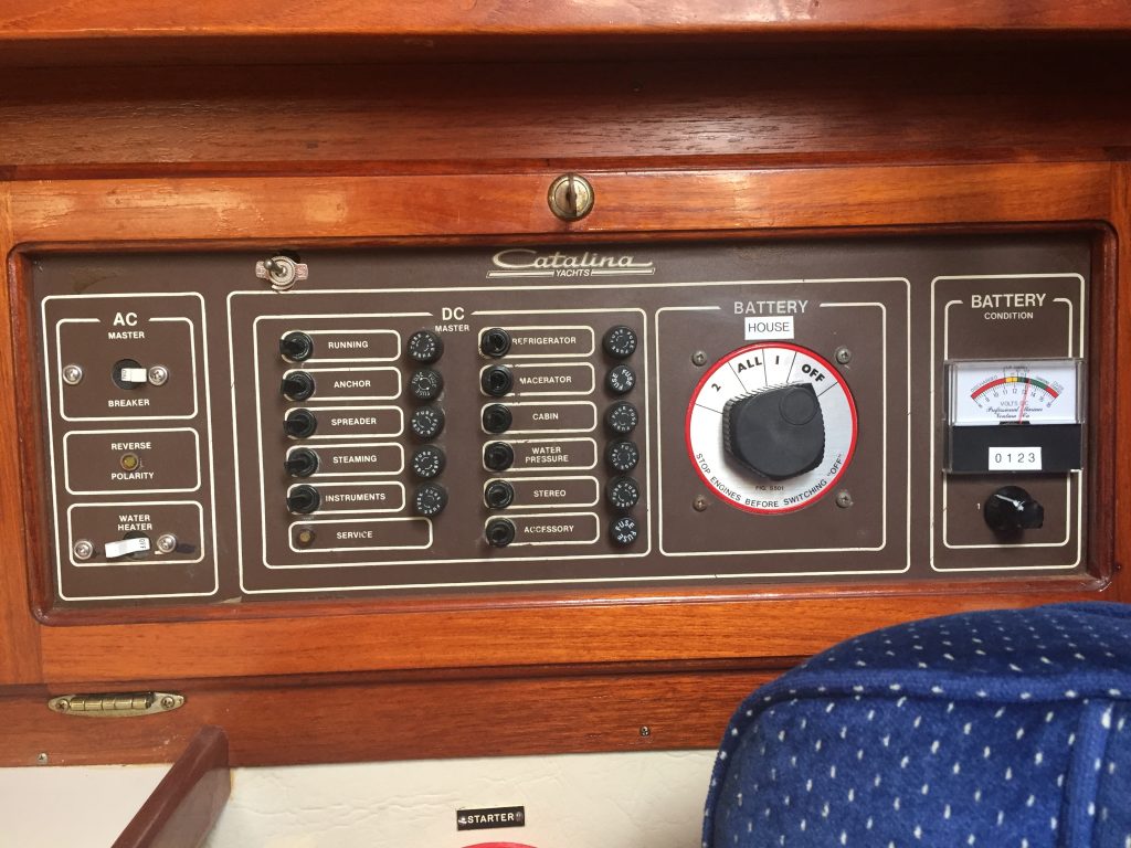
One of the first projects I added to my to-do list was replacing the original electrical panel. There were so many things wrong with it that it is hard to list them all, but I’ll try.
- It used fuses instead of breaker
- The fuse holders were cracked and could no longer be sourced
- Several switch had been replaced with ones that did not match
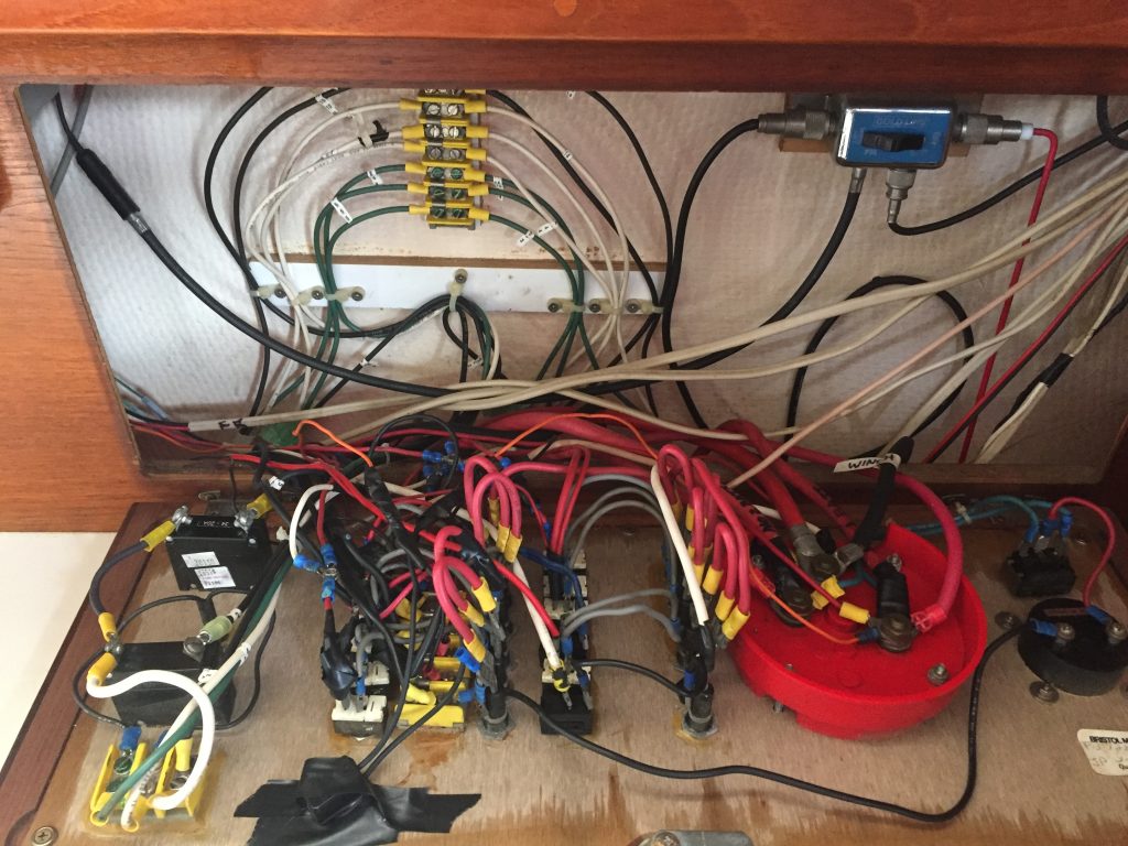
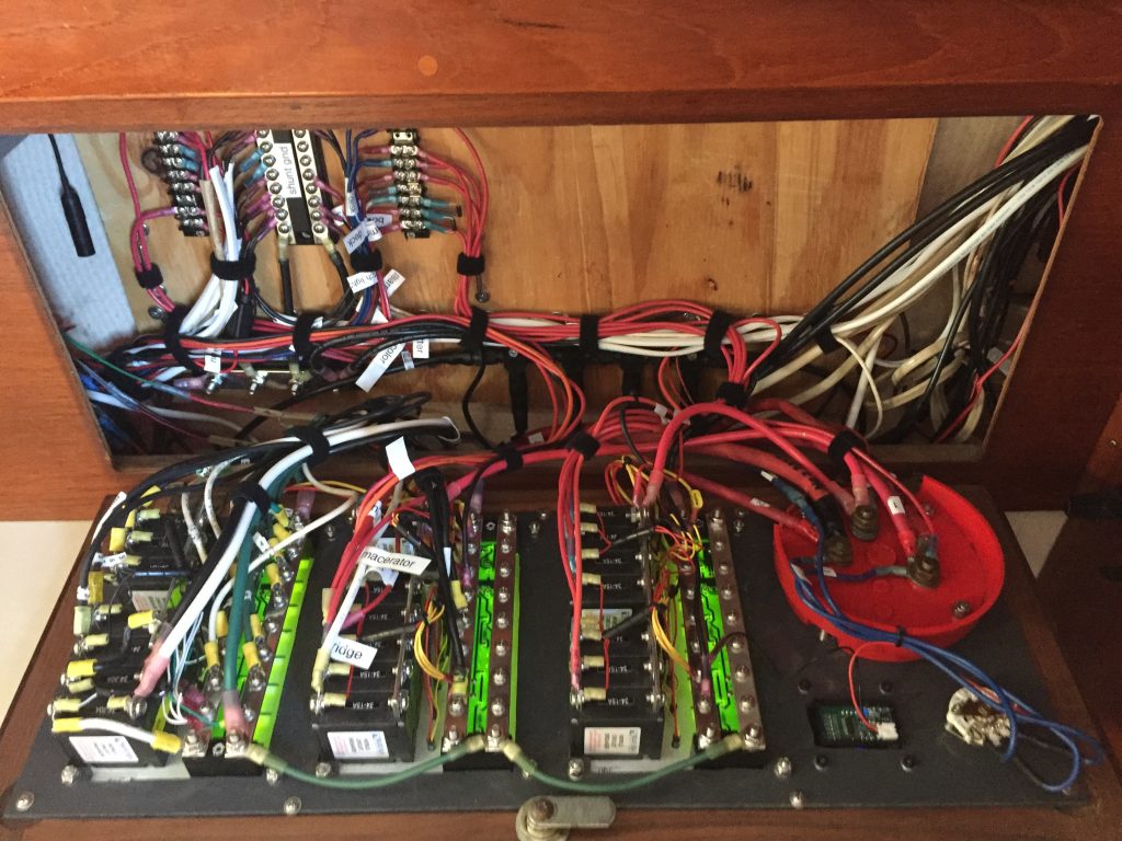
- The wiring was a rat’s nest
- The spade connectors were flakey and kept losing connectivity. Our new electronics were not happy when they momentarily lost power every time we hit a wave.
- The entire panel fed from one small source wire
- There were not enough switches for all the systems I wanted to add
- The labels did not match the circuits I needed
- It looked worn and dingy
- The AC side only had a single-pole switch which is not to current code
- There was no way to separately control the fridge or battery charger
Options
I initially thought I would build my own panel from scratch, but I knew that getting the breaker slots cut out and aligned was going to be a real challenge without some kind of CnC. I then started looking for modular panels that I could use to build what I wanted. These turned out to be very expensive, and still did not do what I wanted. They also did not fit the space well.
I knew if I had to, I could cut out a bigger opening and build a new hinged frame, but I was really hoping to reuse the original to keep the look consistent. I finally found some panels that were really close to the size I needed, but were just 3/8″ too large. I figured I could make them work.
Removal
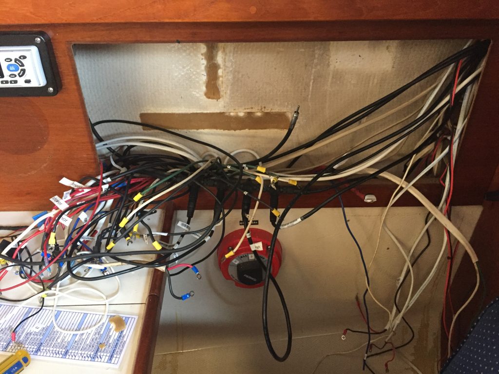
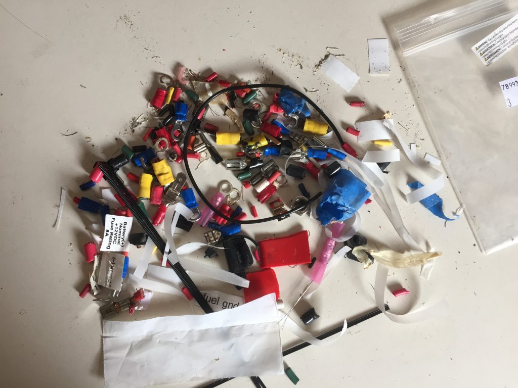
Once I was ready to start, I labeled each wire before disconnecting it, then unscrewed the old panel hinges and lifted it out. I also removed all of the terminal blocks and other miscellaneous items that were attached to the hull behind the panel. Of course I shut off the shore power and disconnected the batteries before I started this process.
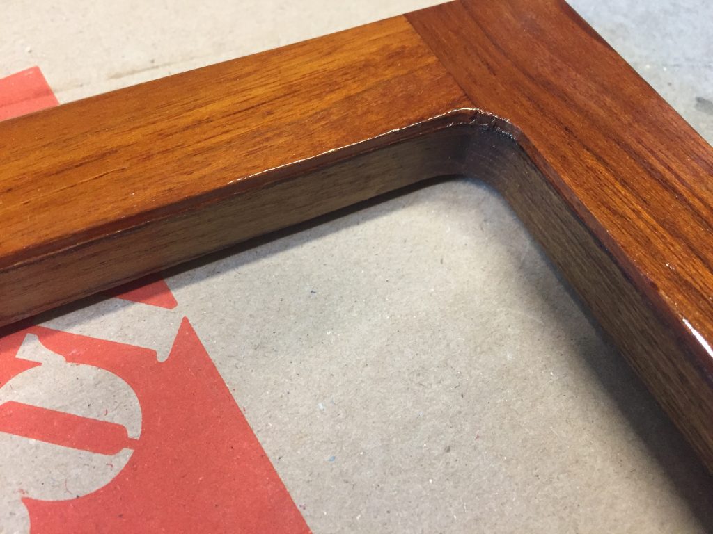
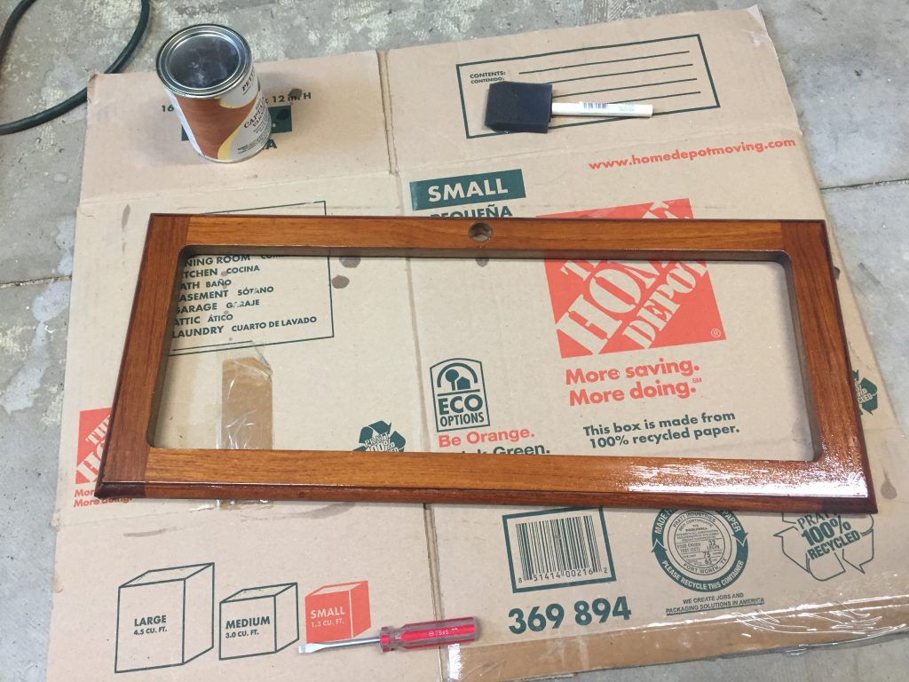
Resize frame
To solve this size issue, I used a router with a flush bit to remove the curved edge from the inside of the wooden frame. There was just enough of a lip for the router guide wheel to hit, so it was actually pretty easy to get a nice clean edge. That was just enough to give me that extra 3/8″, and the new panels fit beautifully. A few coats of varnish, and you would never know it had been modified.
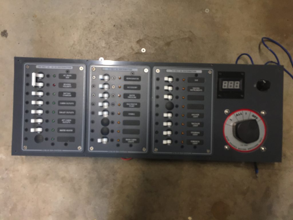
New panel insert
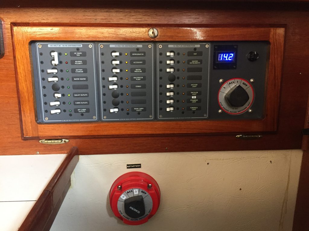
For the new layout, I wanted 1 AC panel, 2 DC panels, and room for the battery selector switch and volt meter. Some of this would be purchased panels, and some would be custom items, so I needed to make an insert for them all to attach to. I used grey plastic and cut out the holes using a drill and jigsaw, then mounted all the parts into place.
I used Blue Seas panels (AC and DC) as the basis for main switch panels.
- AC: https://smile.amazon.com/dp/B0000AXNUY
- DC: https://smile.amazon.com/dp/B000K2MAYW
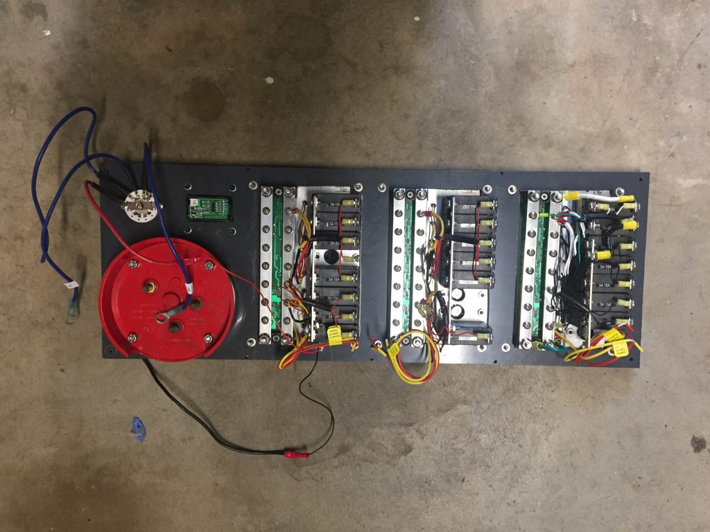
Assembly
With all the parts in place, the whole insert could be screwed to the frame and some of the basic wiring done. Next I reattached the hinges and mount the whole panel back in place.
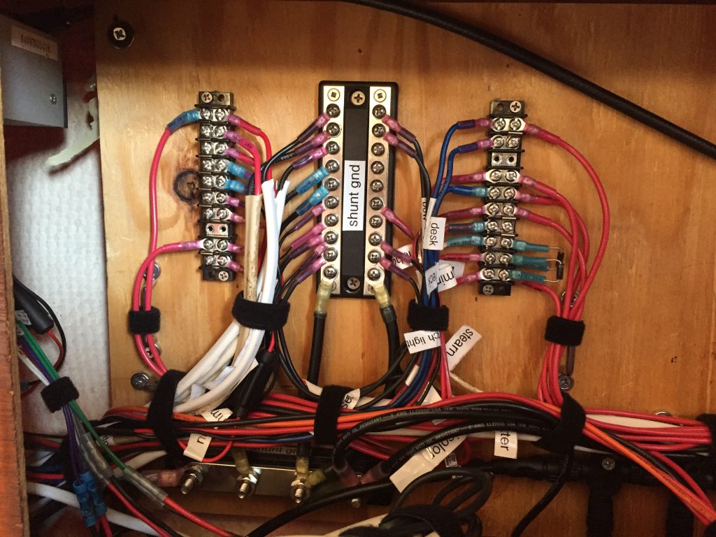
New mounting board
I didn’t want to have any splicing at the panel itself, since that had caused issues before and was hard to debug. So I epoxied four small blocks to the hull and screwed down a piece of plywood that I could use to attach terminal blocks and other accessories.
Wiring
Before starting the project, I had created a schematic of every circuit and wire, so I knew where everything went. I took each wire, cut off the end, and attached a new crimp-on connector. I used ring connectors for most wires. All new connectors were heat-shrink, for a nice solid and sealed connection.
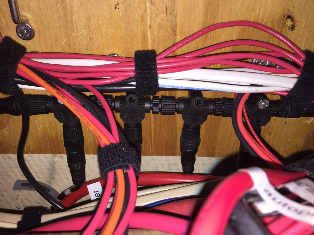
If any wire needed to be relabeled, I did it as I connected it. I also tried to run the wires so that there would be as little bend as possible when the panel was hinged open. I added some tie-downs to the mounting board to give me a place to route them cleanly. Velcro strips made it easy to keep everything neat, but still accessible.
See the electrical schematics for details on the wiring.
NMEA network
I used the mounting board as a place to attach the network cable tee fittings. They are held securely in place, are easy to get to, but out of the way. See the electronics network schematics to see where this backbone fits into the overall system.
Final result
I am very happy with the new panel. It solved all of the issue with the original panel, I have a couple of extra circuits for future, and it looks great.


