The choice of replacement engine was mostly driven by space and mounting considerations. The Mark I C36 has engine mount stringers that are spaced for the Universal M25XP, which has the same spacing as the old Atomic 4 engines. The Beta25 had an option for Atomic 4 mounting brackets, which the Beta30 did not. So, the B25 would require much less rework of the stringers. (For newer C36 owners that have the M35, the Beta30 may be an easier fit)
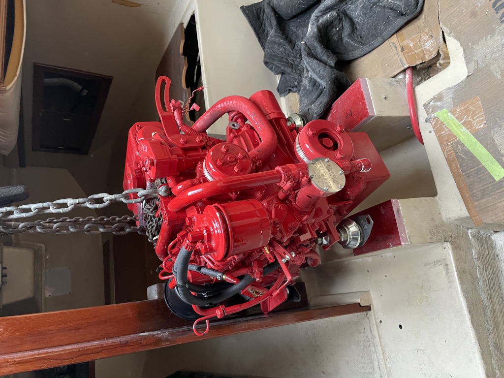
Even though the B25 had the same mounts, was still not a drop-in replacement. The vertical distance from the mounts to the transmission output is not the same as the Universal engine, so I had to add raise it up 3/4″ to get the alignment right. I also moved it forward about 1/2″ to give more room for the shaft seal, and to allow for easier access to the air filter.
To get everything aligned and to figure out where we needed clearance, I set the engine roughly in place, then cut and trimmed wooden blocks until everything aligned and provided room for fittings and hoses. I had to turn a couple of the mounts a bit to get them to fit, but once that was all figured out, the wood blocks then became the templates for the next phase.
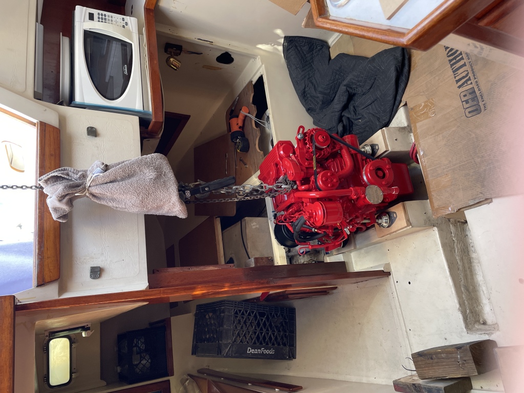
To make it easy to move the engine in and out of place, I rigged a sling from the boom and used a small chain fall to hoist the engine.
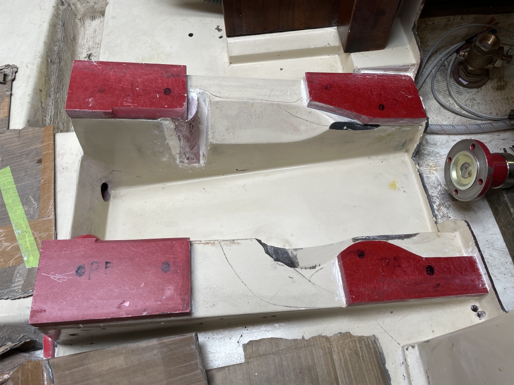
For the final shim blocks we used GPO-3, which is a high-density fiberboard that can be worked like wood, but can also be machined like metal. They were fixed in place with a strong adhesive called Plexus.
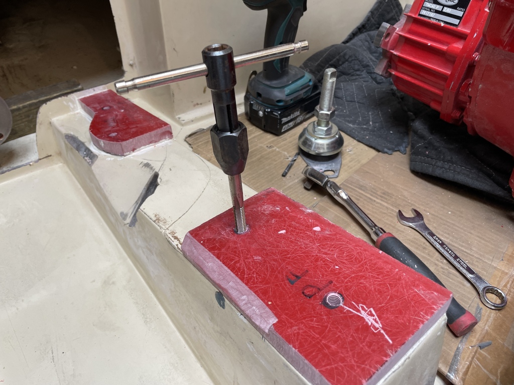
Once the shims were set, I then put the engine back in place temporarily and marked the holes for the mounts. The original engine was held in place with lag screws, but I wanted something more solid, so I drilled and tapped the GPO-3 for 3/8″ machine screws.
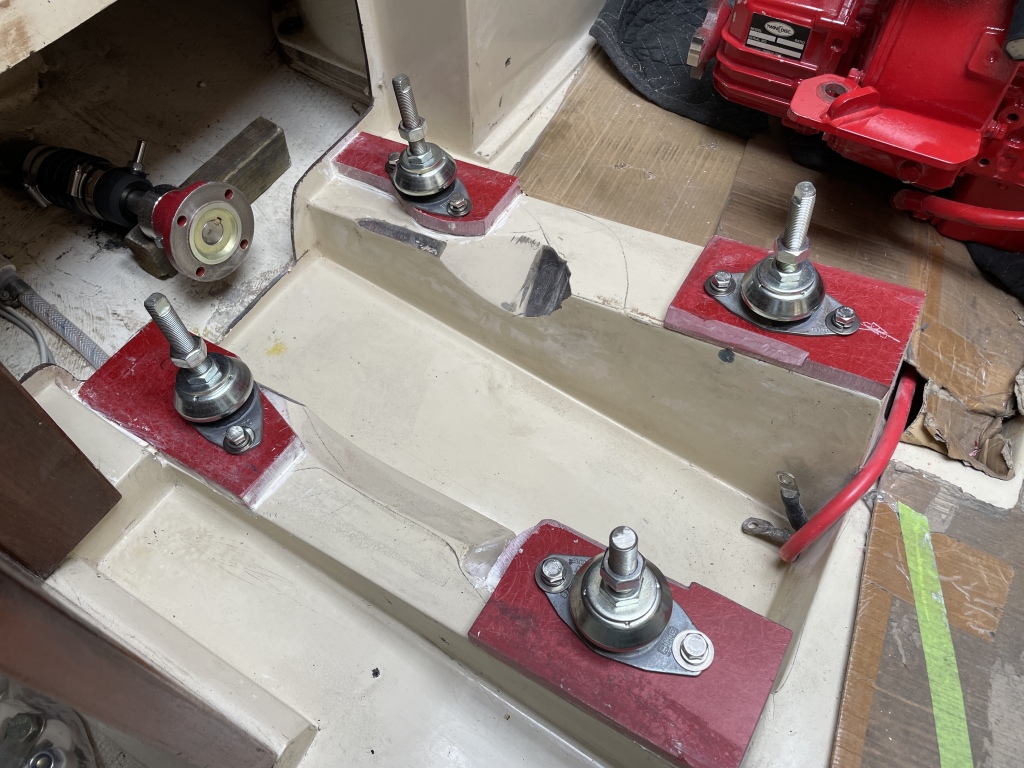
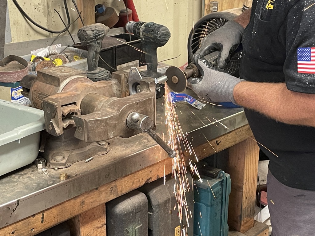
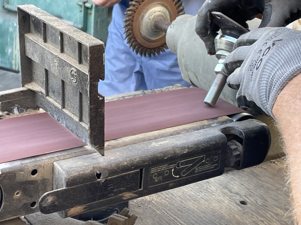
One of the mounts had to be cut down so it did not hit the fuel pump. A cutoff wheel made quick work of it, and a quick sanding of the end meant the nut could go on easily. I also chose to change to use regular nuts and lock washer rather than the supplied lock nuts.
All of the initial alignment and fitting was done with the boat on the hard, which meant we could move the shaft in an out easily and not worry about flooding. The downside is that the boat has a different shape when sitting on stands vs sitting in the water, so I needed to make sure we had adjustment room in all of the mounts to do a final alignment once the boat was back in the water.
Then end result turned out great. Even when back in the water, I was able to get it aligned in both pitch and yaw to within .001″ of the shaft flange.


