Intro
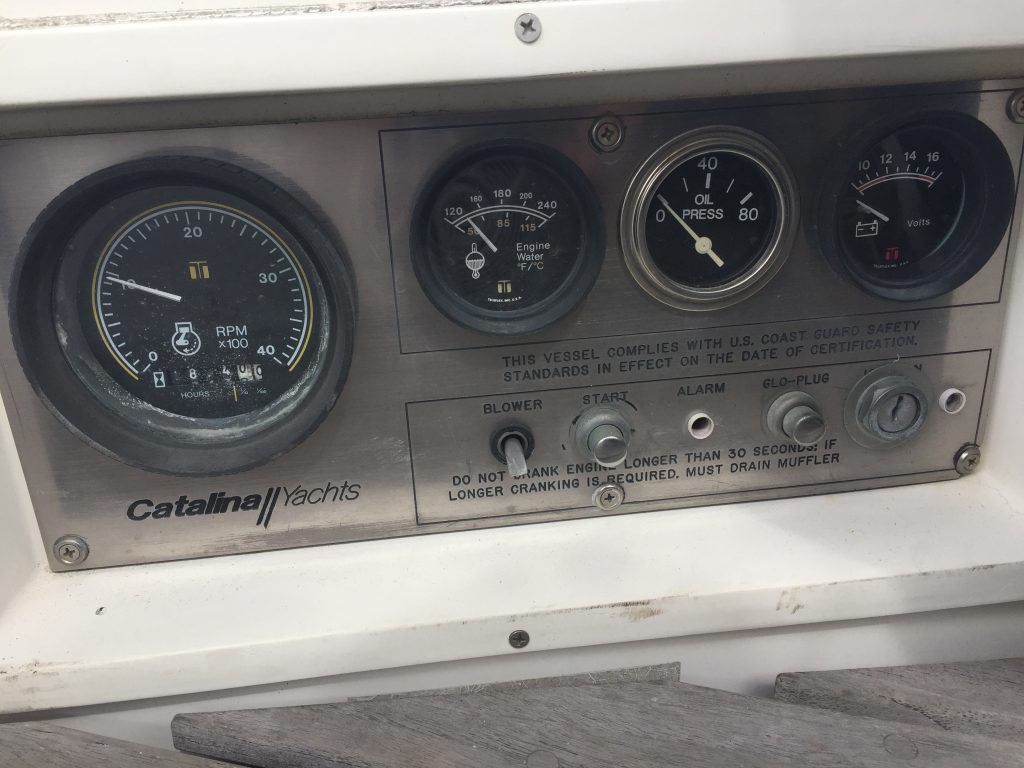
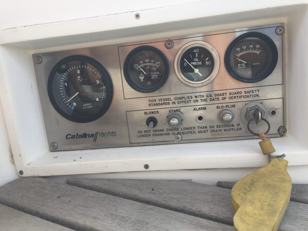
When we did our sea-trial, we noticed that the engine was only getting up to 2200 RPMs. But from the sound and speed, we were pretty sure this was not correct. Since we didn’t use the tach much, we didn’t really worry about it. Also, the engine hours meter on the tach was broken, and one of the previous owners had installed a new meter in the lazarette.
Calibration attempt #1
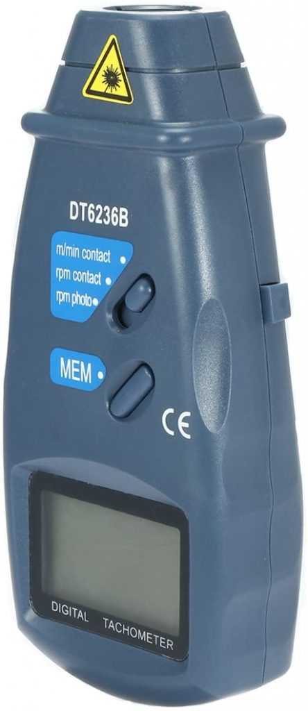
Eventually I decided to calibrate the tach. I bought a digital tach, and tried to get real RPM readings from the engine. This particular tach did not have a laser pointer to see where it was aimed, and I could not get anything useful with it. The readings would bounce all over and usually outside of any possible range for the engine, so I shelved the project for another time.
Calibration attempt #2
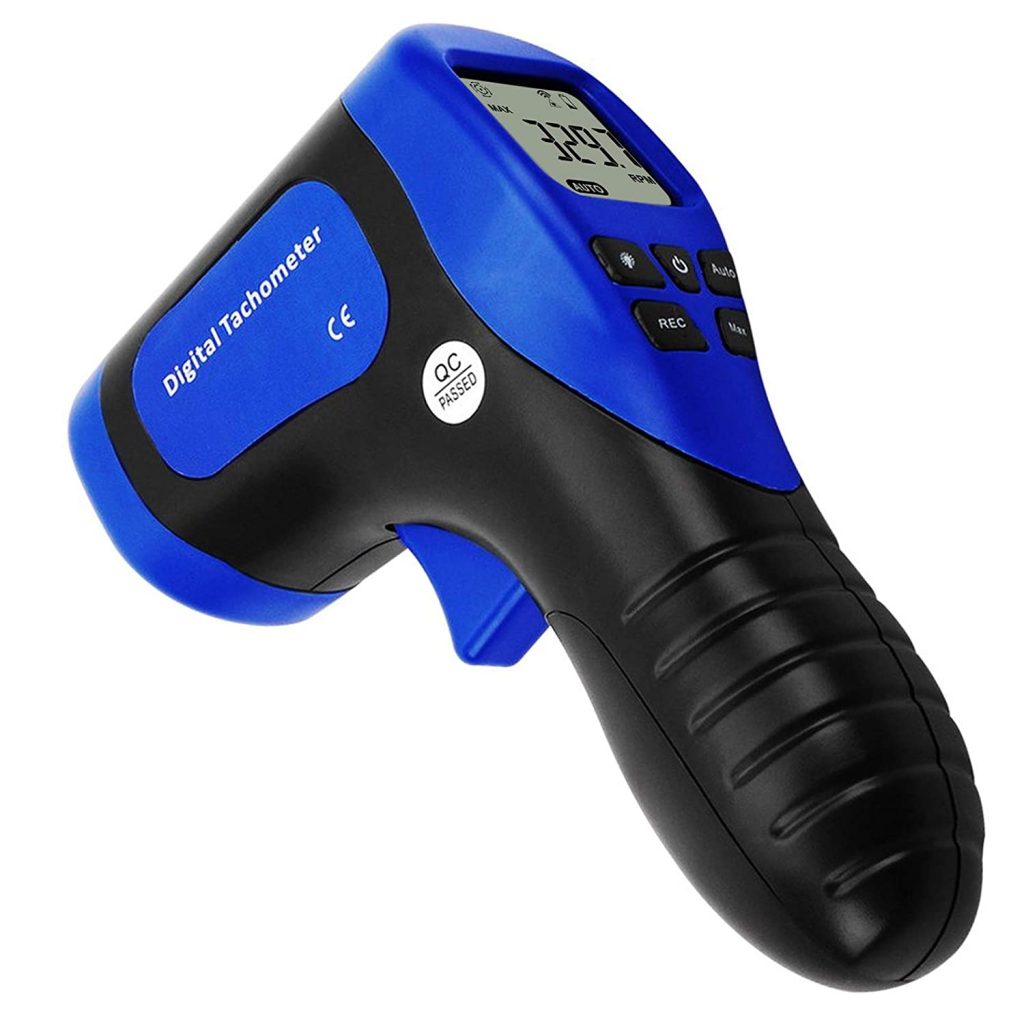
Several months later, as the list of project got smaller, I decided to try a different digital tach with a laser pointer. I did put a small piece of the reflective tape on the main shaft, and covered the rest of the shaft with black electrical tape to prevent stray reflections. With this setup, I was able to get good readings, and I could even do it from the cockpit by leaning in the main hatch and aiming the tach straight down onto the shaft.
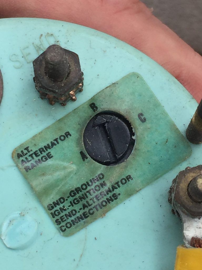
With this setup, I took readings at several different RPMs and compared them to the boat’s tach. Some were high, some were low, some were about right. There seemed to be no pattern. I suspected that the settings on the tach were wrong. I tried each of the three settings (A,B,C) and found that C was the closest. Then I tried to use the tiny calibration screw to dial it in, but as soon as I tried, the screw disintegrated and the tach stopped working completely.
Sigh… Time for a new tach.
New tachometer
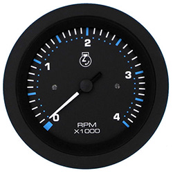
Luckily, it was time for Defender‘s annual warehouse sale, so I found a tach that looked like the right size and scale, and said it was appropriate for diesel engines with alternator output signal.
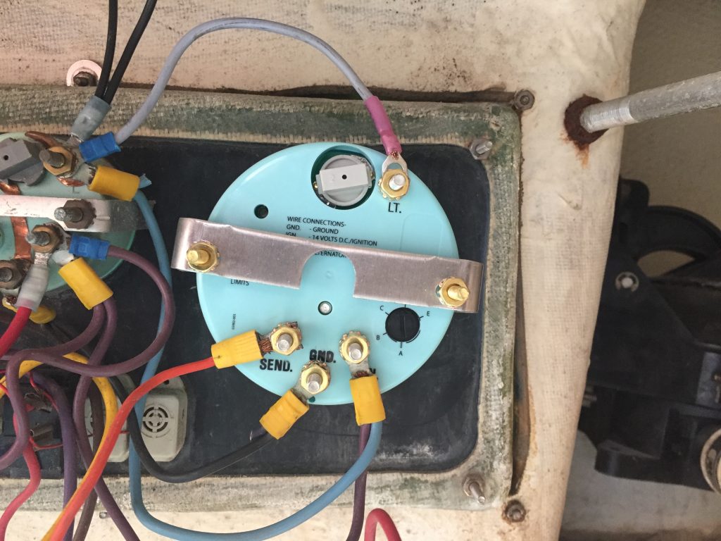
Installing the new tach and putting the wires back one was pretty easy. I did have to make one short wire for the light input, since the old tach had the wires integrated with the lamp.
Calibration attempt #3
The tach instructions had a chart the switch settings (A,B,C,D,E). You just look up the number of poles on the alternator and the pully ratio. Unfortunately, the chart was useless for such an old engine and alternator.
Since, there were only 5 options, I just tried each one until I found the best match to the digital tach. Then it was a quick adjustment on the calibration screw to get it spot on. Now the readings are within a few RPM across the entire range of the engine.


