Intro
Shortly after purchasing the boat, we installed a completely new set of electronics. Unfortunately, the budget at the time did not include an auto-pilot, but we knew we would do it eventually, so we planned it into the design. Fast-forward one year, and it was time to add the AP.
Electronics
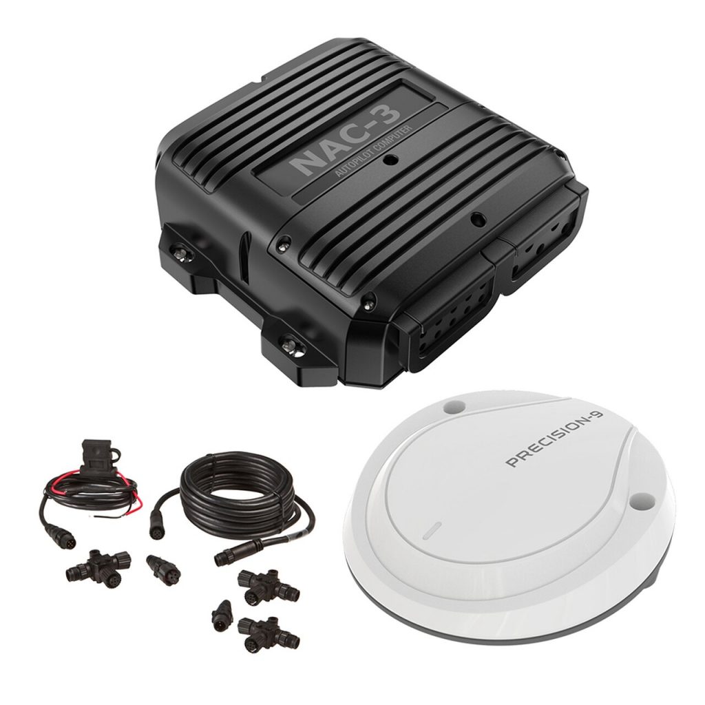
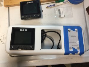
Since everything else was B&G, it was a no-brainer to use the B&G controller. Based on the size of drive we would need for our boat, it was pretty clear that we would use the NAC-3 and its associated core-pack and keypad.

Drive unit
The harder choice was the drive unit. I had assumed I would use either a hydraulic or electro-mechanical ram. I debated between the Raymarine and B&G units, but eventually decided I would stick with B&G. That way if there were any issues, there would be no finger-pointing between vendors.
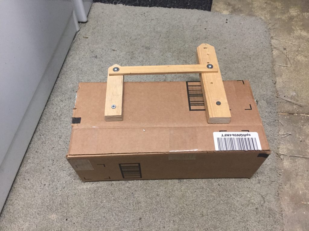
With that decision in mind, I got the specs from an online manual, and made a mockup of the unit to figure out how I would mount it. Once I had the mockup on the boat, it was clear I had a problem. There was one place in the stern lazaret where it would fit, but there was no way to mount the tiller arm so that it would be aligned with the ram. Also, fabricating a mount for the ram in that location was going to be a real challenge.
I saw other people had mounted the ram in the aft cabin, but I really did not want to do that, so I went looking for other drive options.
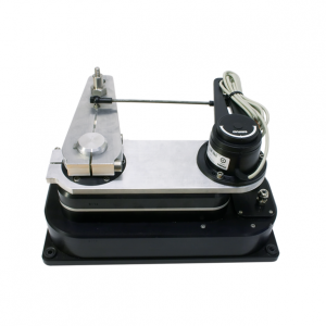
I found the B&G DD15 which looked interesting. It had a much more compact shape, could mount upside down, and seemed to have pretty good reviews. I also like the electro-mechanical clutch that disconnects much of the drive unit from the arm when not in use, so it would not interfere with the feel of the wheel when hand-steering. The DD15 also comes with a rudder sensor, so I could save some $ on the core-pack and also not have to fabricate a mount for the sensor.
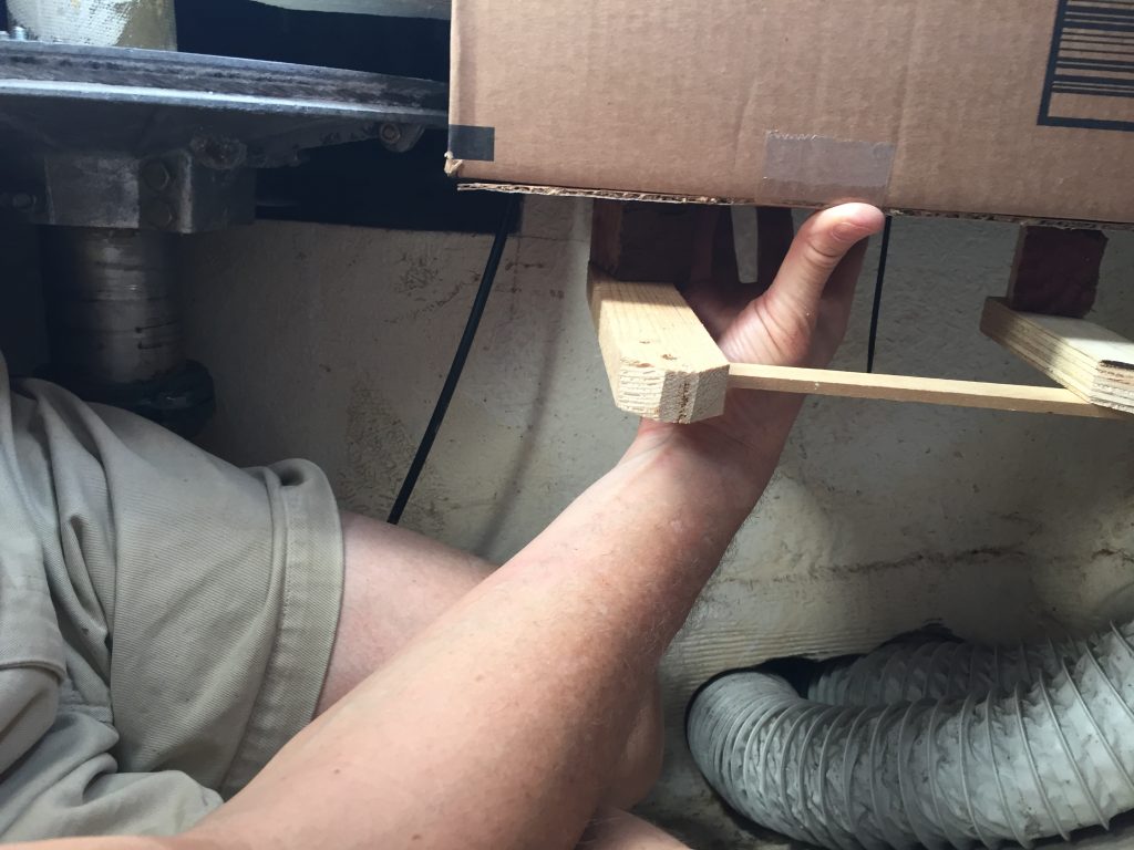
To make sure it would works, I made a mockup of the DD15, and when I took it to the boat, I was pleased to see that I could mount it in a way that would align nicely with the tiller arm.
Install controller
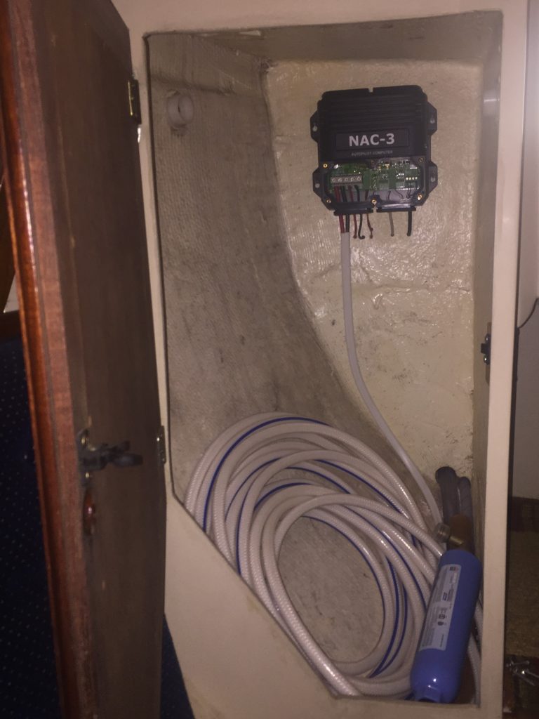
I had originally planned to mount the controller behind the electrical panel, but it turned out to be much larger than I thought. Also, the drive unit wires were pretty short, and I didn’t want to splice them. I settled on mounting the controller to the back wall of the little hanging locker in the aft cabin. The drive is just on the other side of that wall, so the wires will easily reach.
Once mounted I needed to get power and network to it. The network was easy, since I had a set of connection point just above that locker where the GPS helm connections terminated. I just added one more tee connector and ran a short drop cable to the controller.
For power, I used duplex 8g wire that I ran from the controller, under the starboard bench in the aft cabin, along next to the water tank, then up to the panel. On the new panel, I installed a 30A breaker, where I terminated the power cables.
Install compass
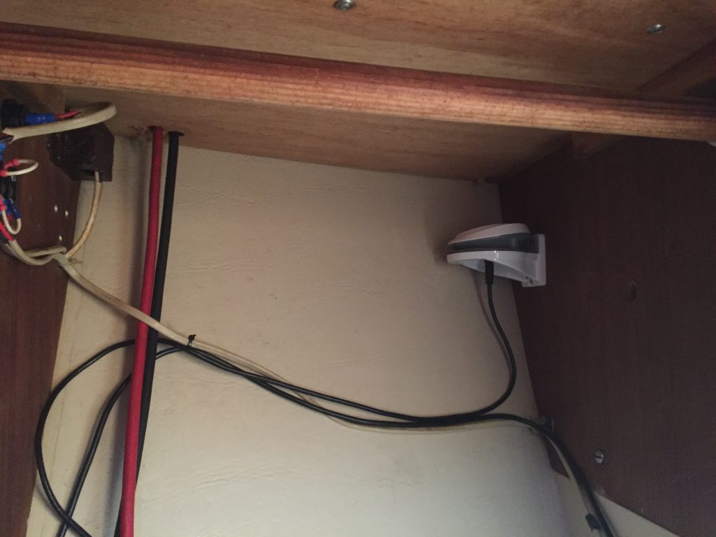
The controller comes with a compass that is more precise and has more axes than the one in the GPS. This compass need to be away from magnetic and electrical sources, and aligned with the centerline of the boat.
I looked at several options for where to put it, and the one that seemed best to me was in the V-berth hanging locker, up in the corner where it would be out of the way. This location also had easy access to the NMEA 2000 network, since there was already a connection point there for the speed/depth transducer.
The network cable that came with it was much longer than I needed, but until I can get a shorter one, I just coiled it up and zip-tied the excess out of the way.
Fabricate mount for drive unit
I spent several days drawing up plans for ways to mount the drive unit. I really wanted to just attach it to the forward side of the lazaret so I could still have lots of room behind it for other access. But I wasn’t sure that would be strong enough to support the weight of the drive and the lateral forces of driving the rudder.
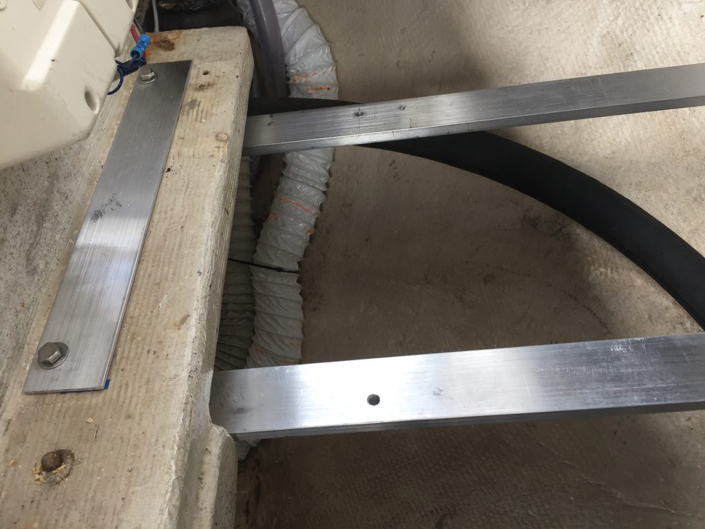
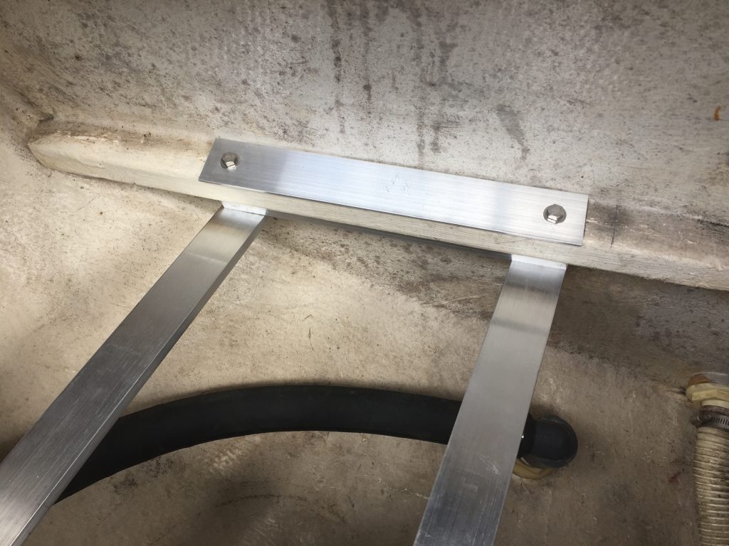
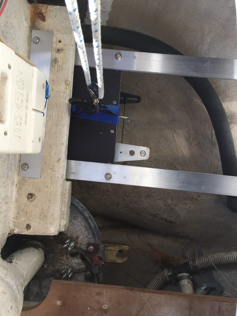
I ended up going with a design that would suspend the drive from two aluminum bars that attached to the glassed-in ledges at the front and back of the lazaret. It would mean that access to the space below would be limited, but it would be very strong and I wouldn’t have to worry about the forces involved.
Normally I would go to our local metal supply store and pick through their scrap bin for the parts I need, but since this was during the Covid-19 lockdown, that was not an option. I ended up ordering aluminum stock on eBay and it arrived in about a week.
- (2) 2 x ½ x 36 aluminum bars
- (1) 1 x 1 x 36 aluminum square tube (thick walled)
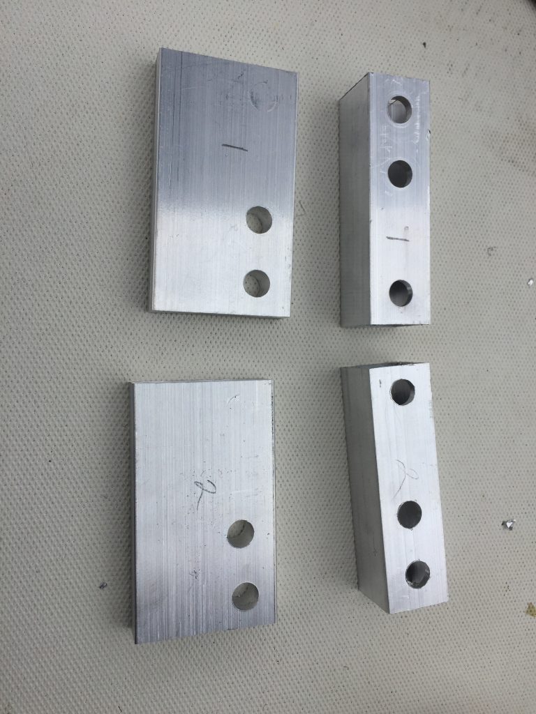
- (4) 2 x 1/8 x 14 aluminum plate
I used the square tube to drop the bars down low enough that the drive would line up with the tiller arm. The plate made a nice way to distribute the load over a larger area on the top of the fiberglass/wood ledges in the lazaret.
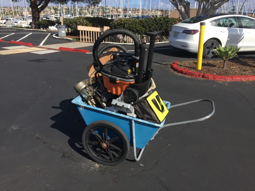
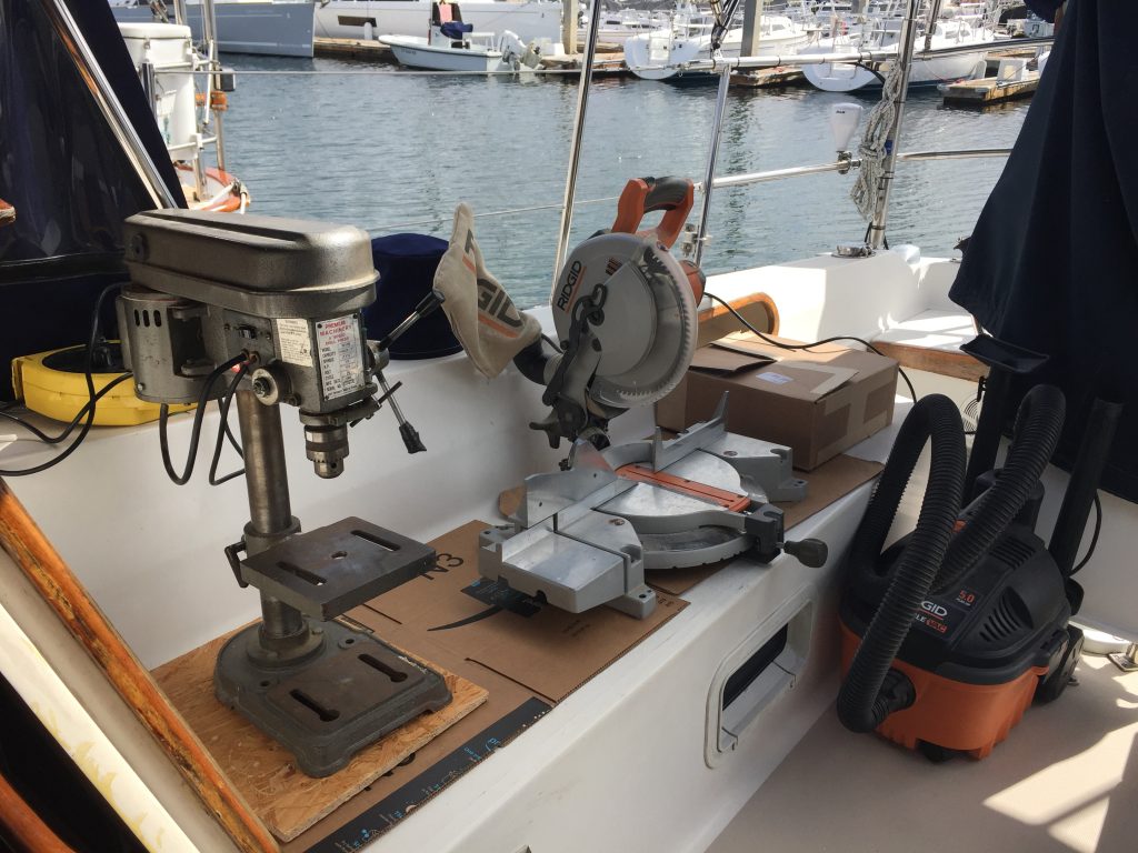
I knew that I would have to do a lot of test-fitting and adjusting during the fabrication process, so I took all my tools to the boat, and set up a metal working shop in the cockpit.
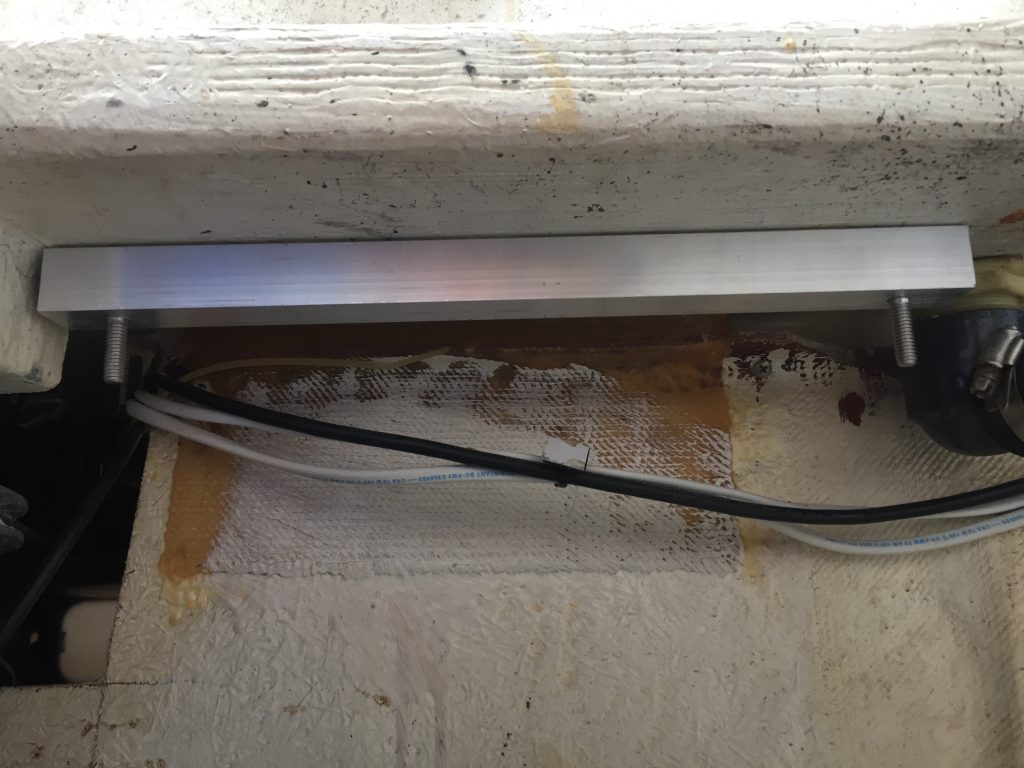
The only real gotcha was that the aft ledge is angled downward, so drilling those holes was a little tricky. Luckily, aluminum is easy to drill, so I just guessed at the angle, held up one end of the bars and used the drill press to get it close.
With the mount securely in place, I was able to measure and mark for the holes where the drive would attach. The instructions for the drive unit are very specific about the placement of the drive in relation to the tiller arm. For the drive to work properly, this has to be pretty precise. With the use of squares, tape measure and paper cutouts, I located where the center of the drive arm needed to be, and marked the hole locations.
Since two of the holes were under the fiberglass ledge, I removed the bars to drill them in the drill press.
Test fit drive and tiller arm
With all of the parts ready, I started a test install. First, I loosely attached the tiller arm to the rudder post, while I still had room to work in the lazaret. Then I reinstalled the mounting bars, but did not tighten them yet.
Since the drive unit is pretty heavy, and would need to hang under the bars, I needed some way to hold it while I did the install. It turns out that our dingy engine hoist is in the perfect place for this job. I wrapped some webbing straps around the drive, hooked it up to the hoist, and lowered it into place. Once under the bars, I rotated into position and winched it up into place so I could insert the bolts.
With everything in place, I snugged up the bolts holding the bars and the drive.
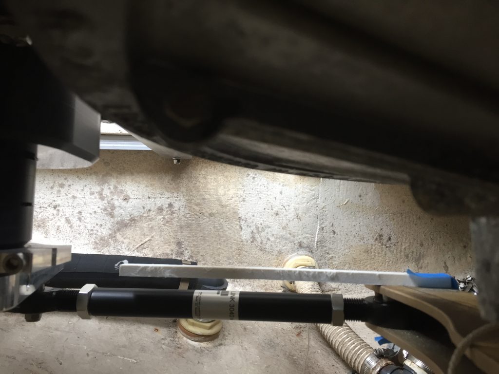
I attached the drag-link to the drive, then roughly set the length and attached it to the tiller arm. Next, I tweaked the height of the tiller arm so the drag-link was aligned with the plane of the drive unit. Then I adjusted the length of the drag-link so the rudder and drive unit would both be centered at the same time.
New rudder stops
With the test fit done, I slowly turned the wheel to make sure everything worked smoothly and stayed in alignment. You have to be careful that you don’t turn the rudder too far, because it will over-rotate the drive unit. The instructions list the maximum angles, and the stock setup of the rudder will go more than that, so you should not turn it all the way. Once I was sure everything was going to fit OK, I needed to make new rudder stops to limit the turn to the max the drive can handle.
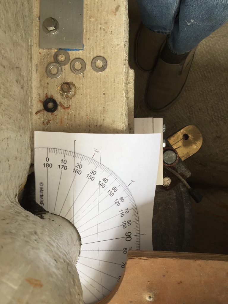
I used two methods to get it right. First, I made a paper compass marked with the max drive and rudder angles. I also used the alignment of the drag link to determine the max rotation. When the drag-link is parallel to the edge of the drive unit, that is the max allowed.
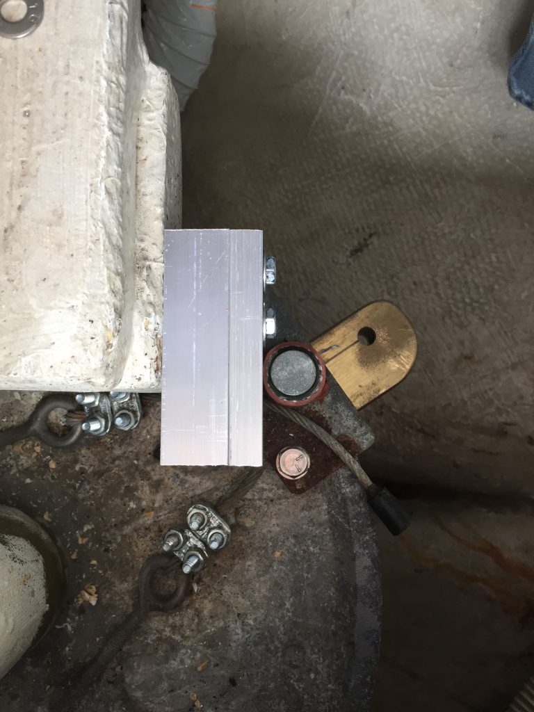
Once the rudder was in the max position, I measured the distance from the stop post to the fiberglass ledge. I then used some of the leftover aluminum tubing and bar to make new stops that I screwed to the ledge.
Install tiller arm
To get access to the tiller arm, I cut a hole in the back wall of the aft cabin, and made a piece of plastic that screws on to cover it. I also removed all of the drive and mounts to make it easier to work on the tiller arm from the lazaret side as well.
Next, I installed the tiller arm at the right height to line up with the drive unit and drag-link. Then I double-checked to make sure it was aligned with the rudder.
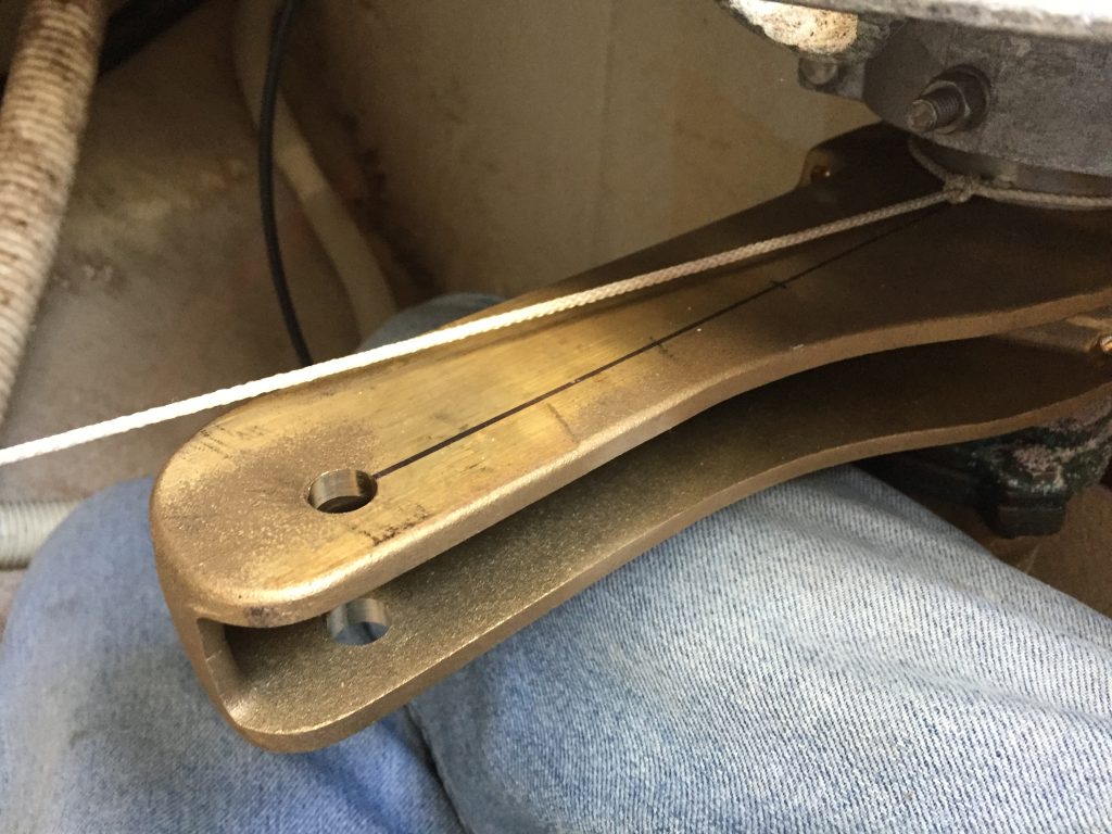
Now all I had to do was drill the hole through the rudder post for the bolt that keeps it from slipping. The tiller arm comes with the hole pre-drilled on one side, but not on the other. They say in the instructions that it is nearly impossible to get the hole drilled to line up perfectly, so you need to drill through the post first, then the other side of the tiller arm. That way the entire hole is aligned so the bolt will go through. If you are off a little bit, it doesn’t matter, as long as you are not so far off that there is not room on the other side for the nut to go on the bolt.
I knew that the process would likely wear down the drill bits, and that normal bits would not reach all the way through the tiller arm on the other side. So, in preparation, I had purchased two long 3/8” drill bits, and had my corded drill with me so I didn’t have to worry about battery life on the cordless.
I had heard from other people that drilling this hole was a nightmare, but I figured with the right tools and good access that it should be easy. Wrong! It took me more than 3 hours, 3 uninstalls, and a lot of bruises to drill that one damn hole.
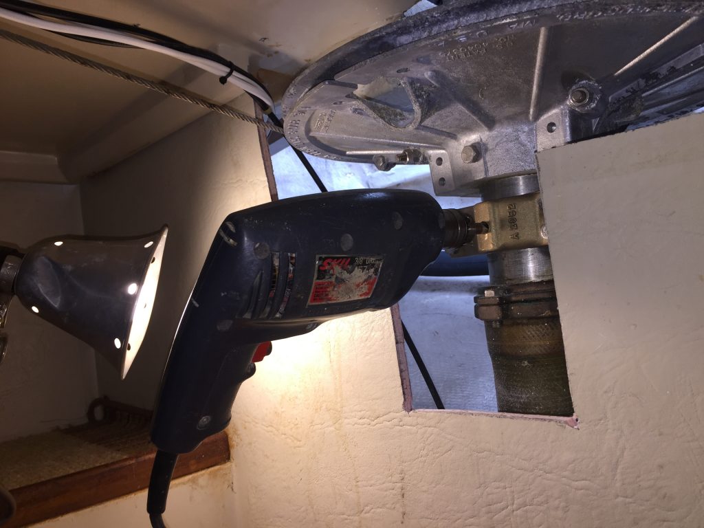
The long drill would not make any progress on the rudder post, so I switched to a different bit for that. It was hard to get any pressure on the drill while lying prone in the aft cabin. I tried several different positions over the next 2 hours to wedge myself in and bring some force to bear. Eventually, I got through the post. At that point, the short bit would not reach much into the bronze, and was pretty dull, so I switched back to the long bit. I could not tell if I was making any progress, so once I was sure I had the hole started in the bronze, I removed the tiller arm and took it up to the cockpit workshop.

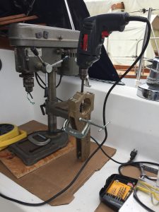
The tiller arm was too tall to fit in the drill press, so I clamped it in a vertical position and used the hand drill to finish the hole
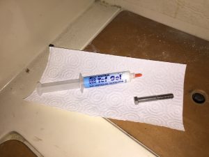
Turns out I was not very good at judging my drill alignment, because when I went to reinstall it, the holes did not line up. Luckily with the misaligned hole already there, I was able to redrill the bronze part pretty easily (20 minutes) with the arm in place. Once that was done, the bolt slid in and there was just barely enough room on the other side to get the nut on. I used Tef-gel on the nut so I would not have issues getting it off in the future if we ever need to work on the rudder.
Attach rudder sensor
The DD15 comes with a rudder position sensor and hardware to mount it, which is a nice touch. It can mount in several orientations, so I had to find the one that worked best for our setup and then cut the sensor drag-link to the right length.
I was stupid and tried to cut it using my power miter saw. The blade grabbed the rod, bent it, and threw it across the cockpit. Luckily it missed me and there were no serious injuries or damage to the boat.
After properly telling myself how stupid I was, I used a hack saw to cut it, and bent it back into shape with some clamps.
With the sensor and drag-link in place, it was just a matter of fine-tuning the length of the rod to get the sensor and drive arm to line up to center at the same position.
Install and wire drive unit
At this point, the drive was ready for final installation. I used the dingy engine hoist again to lower it into place, and bolted everything up loosely. I put Tef-gel on all of the Nylock nuts to prevent seizing and to make installation easier. Once I was sure everything fit correctly, I tightened up all the bolts, and reinstalled the drag link to the tiller arm. I then tested the movement and the new rudder stops to make sure everything worked smoothly and stopped at the correct angles.
From the aft cabin hanging locker, I drilled holes for the drive, clutch and sensor wires. I ran the wires to the controller and connected them per the instructions. I then coiled up the excess wire in the lazaret and zip-tied it all neatly out of the way.
Install controller keypad
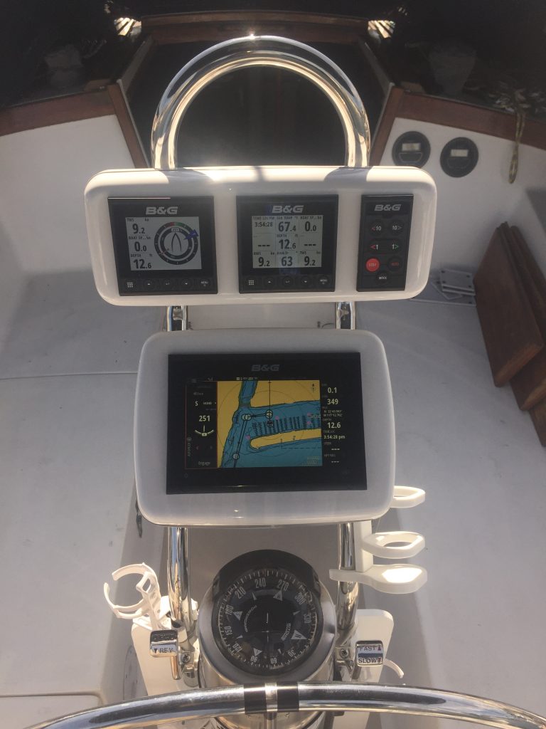
In our initial electronic install, we had left a space on the helm Navpod for the auto-pilot keypad. I removed the pod face, disconnected the network cables, and took it all home to work on.
I used the paper template that came with the keypad and taped it in place to get the position and spacing right with the other displays. I then removed the on other displays, and used a drill and jigsaw to cut out the space for the keypad and drill holes for the mounting screws.
Then it was just a matter of screwing all of the items back into place, adding a tee connector and short cable, and reconnecting the network cables to the displays and keypad.
Back to the boat, connect the network cable, and reinstall the face to the Navpod.
Setup and calibration
Dockside
Once everything was wired up, I followed the instructions for the dockside commissioning. This started with making sure the MFD saw and used all the correct sources. In this case, it was set to use the NAC-3 for AP controller and rudder feedback, and the Precision-9 compass for direction, yaw, and heel.
Then it asked me to turn the wheel all the way in both direction and enter the rudder angle at each stop. With that info, it then ran an automated test and did its initial calibration.
I have to admit that I did a little happy dance when it actually turned the rudder and it was quiet and smooth.
Sea trial
Since we are still in Covid-19 lockdown, we have not been able to do the sea trial and calibration. More updates to come once we can get back out on the water.


